List of drawings you need from an Engineer or Architect if you are building a house in a small city
- Sayanika Das
- Jun 19, 2025
- 6 min read

Drawings are the most important aspect of construction. It conveys the idea into a structural reality. Without a proper drawing, a construction can never be started.
It is a well-structured plan that provides accurate measurements regarding the building. These drawings communicate ideas, design intentions, and probable problems. Although there are numerous types of architectural drawings, but we will only cover the most important drawings needed for the house construction.
What are the List of drawings you need from an Engineer or Architect for construction?
There are various types of drawings that conveys essential information for a building project. Let us look:
Architectural Drawings
Structural Drawings
MEP Drawings
Miscellaneous Drawings
Let's try to understand these drawings and their content and how it helps in executing the actual work on site.
Architectural Drawings
Architectural drawings are technical drawings that are prepared before commencing the construction. These drawings are made with lines, projections, and on an accurate scale. Other drawings that fall into this category are:
Concept Drawing—These drawings are made by architects before the start of construction. They are either hand-drawn on pen and paper like sketches or digitally made using some software. These are not very detailed, but they convey the visual idea of the building. They help owners visualize their houses or spaces in a rough sense. The concept drawings often includes draft floor plan concept or sketches of the spaces from different angles. It helps to set the initial idea and the conceptual direction as per clients design direction.

Concept Drawing | Image Source- Monarch Innovation Site Plan- A site plan offers Bird 's-eye view of the building. Along with the building structure, it also portrays additional structures. It illustrates the full scope of the project, including topography, pavement, trees, nearby roads, etc. It also highlights the access points and the neighboring properties connected to the building. These are the major things that are often part of the site plan and are shown: 1. Built-up area 2. Plot setbacks 3. Plot boundary 4. Road direction 5. Main entry and exit point 6. Landscaping and 7. Other topographical annotations if necessary

Site Plan Drawing | Image Source- Archtene Floor Plans- Floor plans are extremely precise as they show how rooms and other spaces are laid out, along with furniture layout. It helps in visualizing space and guides construction as per accurate measurement.

Floor Plan Drawing | Image Source- Cleanpng Cross-Sectional Drawings- These drawing shows the vertical view of the building. It highlights visible components as well as hidden features. It shows how various components fit into each other, thus offering visuals beneath the surface, and within walls and floors. For better clarification architects provide minimum two cross sectional drawings in residential building design, one is through staircase and another is through toilets. These are critical areas where sectional drawings give better understanding of floor levels. Hence always seek these drawings if you're planning to build a house from an architect / engineer.

Cross-sectional Drawing | Image Source- Monarch Innovation Elevation Drawings- These drawings show the overall appearance of the building along with its height and width. It helps engineers and architects understand the interaction of the building's orientation with natural elements like sunlight and wind. Elevation drawings captures the material, texture and the volume / massing of the structure. This gives an initial idea of built form to the client. With the help of a well drafted good for construction elevation drawings the contractor reads all the dimensions of the design as per approved 3D.

Elevation Drawing | Image Source- Monarch Innovation 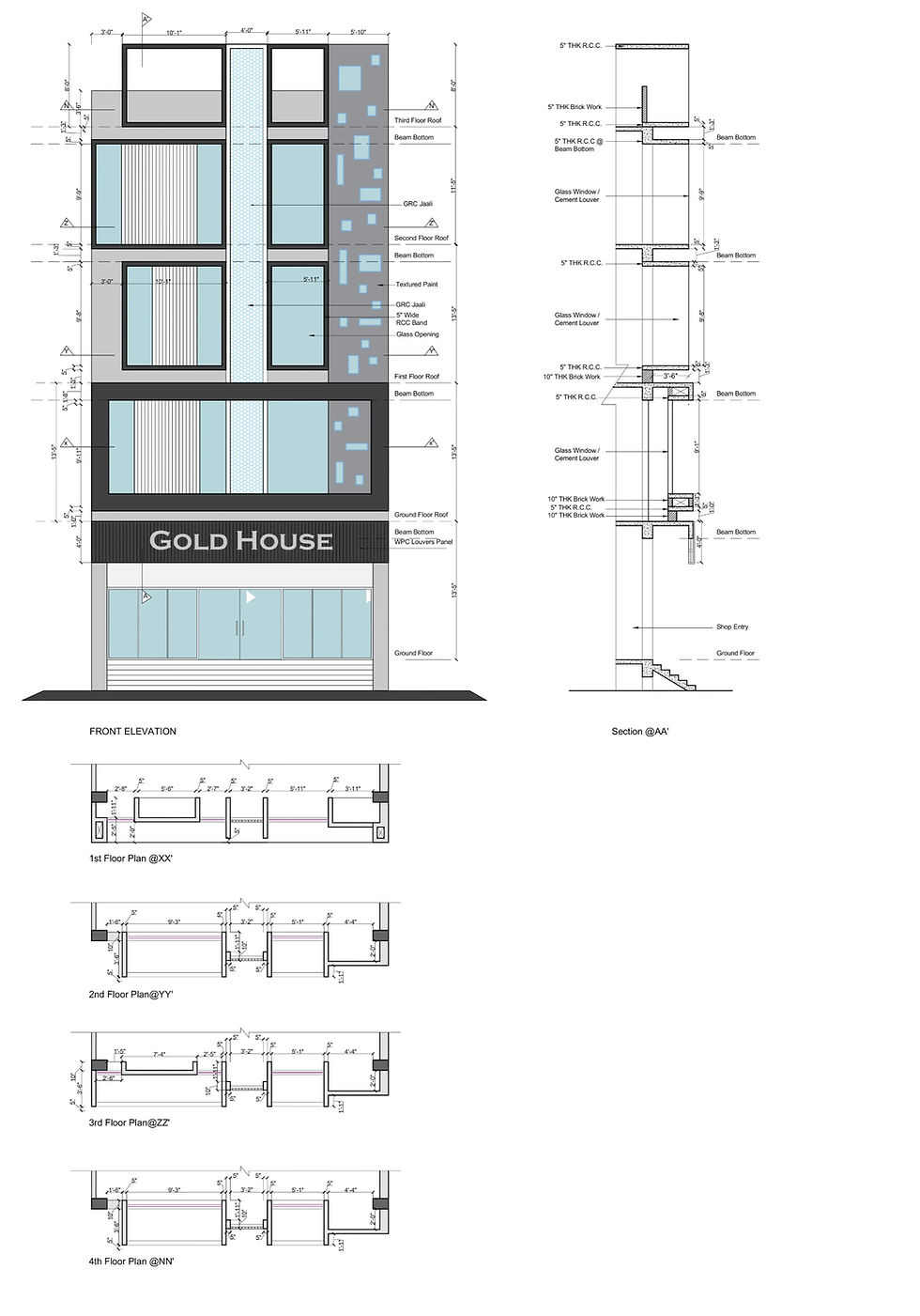
Elevation drawing | VBS Design Studio Door window opening schedule and design- These drawings shows the schedule and position of door window openings in the floor plan. The drawing shows the lintel and sill level clearly as per design. The detailed drawings captures the design of each window and doors as per the specification and discussion with client.

Door Window Opening schedule | VBS Design Studio 
2D Working drawing for door elevation | Source: Pinterest Landscape Drawings- These drawings offer an aerial perspective of the building, showcasing the pools, trees, parking areas, hallways, outdoor feature wall elevation & spaces, roads, and more. Landscape drawings generally encompass all areas outside the building's constructed space. Usually, landscape drawings are a separate task for architects unless otherwise specified.

Landscape Design Drawing Sheet | Source: seasofgreen Working Drawings- All the drawings mentioned above are basic architectural drawings. they are like a guide to the contractors, when everything is done as per these well-coordinated drawings, it ensures high-accuracy, precise, and smooth execution of the construction.
General Notes- These are written instructions that help understand different codes used in architectural details. They help explain things like dimensions, tolerances, codes, and how material should be handled. These notes make the drawings clearer and often include design guidelines, standards, and any updates or changes made along the way.
Structural Drawings
Structural drawings focus on the building's structural elements, such as the foundation, beams, and columns. They act as a guide for the building team during the construction process and are part of the project proposal. Now, let's look at the sub-categories.

Centerline Plan- This drawing plan shows the exact position of the structural elements like foundations and columns, along X and Y axes, using a base level (marked 00 for reference). It also illustrates the building's placement inside the site, indicating how far the building is from boundaries and roadways. This is the very first drawing you would need to execute the actual work on site.

Centerline Plan Drawing | Image Source- Pinterest Excavation Drawings- These drawings highlight the depth and width of the earth that must be dug for a construction. This also depends on type of foundation (Isolated / Raft / Pile)They contain information on how to remove soil, how to dig methodically, and what tools to employ. Safety precautions and site preparation are also covered in these designs.

Excavation Drawing Detail | Source: VBS Design Studio Column Drawings- These drawings help the construction team with proper details of the column as it shows the exact height, width, reinforcement, and ring spacing to be used in the columns for the building.

Column Details | Source: VBS Design Studio Tie beam shuttering & reinforcement drawings - The drawing shows the position of the tie beam / plinth beam in the building as per the architectural floor plan. The drawing shows the details of reinforcement as per the building load.

Shuttering Plan & Reinforcement Details | Image Source: VBS Design Studio Slab shuttering & reinforcement details- As the name suggests, this plan helps in the shuttering of the slab of the building. In simpler words, it shows the size and position of beams, slab projection, and reinforcement details of the slab. The drawing ensure precise work as per the designed elevation and floor plan.

Slab & Beam Shuttering Drawing | Image Source: VBS Design Studio 
Slab & Beam Shuttering Drawing | Image Source: VBS Design Studio 
Slab & Beam Shuttering Drawing | Image Source: VBS Design Studio
Staircase details- This shows the exact number of riser and tread along with the reinforcement details of the staircase. The drawing highlights the R.C.C members along with notes as per the load and architectural parameters.

Staircase section, RCC structure, Staircase working drawing | Image source: VBS Design Studio
MEP Drawings
Electrical Drawings- Using simple lines, symbols, and labels, these drawings help everyone understand how the whole electrical system fits together and works. Electrical drawings describe where the lights, switches, fans, and other electricals will be fitted inside a building. It also shows details about air conditioning, heating, and their load power for the system.

Electrical Drawing | Image Source- House Plan Design Plumbing & Sanitary Drawing- This drawing illustrates where the plumbing fixtures are located throughout the building. It shows the layout of all plumbing elements, including water pipes, drainage systems, toilets, and different types of fittings. It also depicts where faucets and water outlets are situated, enabling everyone to understand how the plumbing system will be linked and positioned within the building.
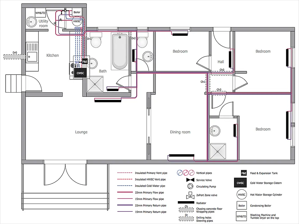
Plumbing Drawing | Image Source- Concept Draw As the name suggests, this drawing works out the drainage system of the building. This drawing shows the movement of water, the locations of pipes and drains, their dimensions, water tanks, and waste flow direction. This help the engineers to understand the drainage system of the building better.

Septic tank and soak pit details | Image source: VBS Design Studio HVAC Drawings- Mechanical drawings, often called HVAC drawings, describes how air conditioning, ventilation, and heating works inside a building. These drawings act as a guide for contractors to guarantee that all elements are set up exactly as planned. They also indicate the placement of air ducts, vents, and controls. These drawings are often not needed unless you're planning for a centralized air conditioning.
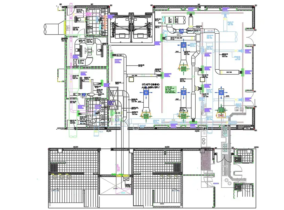
HVAC Drawing | Image Source- Monarch Innovation
Other Relevant Drawings
Submission Drawings- This is the most crucial drawing without which you cannot begin your house construction. Submission drawings adhere to local building codes, are made and sent to the relevant authorities for approval. Clear layouts, elevations, and thorough drawings are included to showcase the architectural design. These drawings include significant technical information, sections, and floor plans. Submission drawings help to expedite permits and approvals, ensuring that construction begins on time and without challenges.

Sanction drawing as per building bye laws | Image source: VBS Design Studio
Conclusion
We have come a long way discussing most important types of construction drawings. If you ae reaching out to any architect or engineer make sure that you get all of these important drawings before you begin the construction process. The drawings will ensure that your building is erected as per the design in a very effective and precise manner. The article is detailed and can be used for study/research purpose.


"Impressive design work — the use of natural materials and balanced tones creates a refined yet welcoming atmosphere. For those interested in exploring more thoughtfully curated home decor concepts, I recommend visiting ttps://cozyabodeliving.com for additional inspiration and resources."
Loved the insights you shared! Quality construction really makes a difference in long-term home value. Vulcan Hats Constructions, one of the trusted custom home builders toronto, focuses on durability, aesthetics, and energy-efficient designs that truly elevate Toronto homes.